Three distinct types of isolation may be used within a UPS system, although how – or even if – they’re implemented depends on the UPS power supply type and the application of UPS. In summary, they are:
- The galvanic isolation between input and output
- The input isolation between mains and battery
- The isolation between the dc circuit and the uninterrupted power supply output
Galvanic isolation
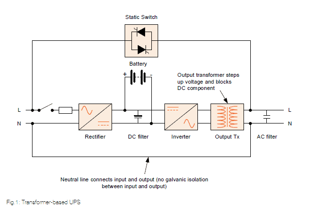
In transformer-based UPS systems the transformer is used to step up the voltage at the output of the inverter to a level compatible with the utility or generator supply voltage.
A common misconception is that the transformer is also used to provide galvanic isolation, but this is not the case. If total galvanic isolation is required between the load, inverter and bypass in either a transformer-based or transformerless UPS system, an additional transformer is necessary for the UPS power supply circuit. The transformer must be designed with adequate insulation to prevent the high voltages present at the UPS power output from jumping between windings and prevent a net dc output component.
Input isolation between mains and battery
In the early 60s, when only open lead-acid batteries were available, galvanic isolation was required for safety reasons. Since the late 80s, when maintenance-free lead-acid or nickel-cadmium batteries came into use, input galvanic isolation was abandoned; it is very rarely found now.
DC component output isolation – transformer-based UPS power supplies
In transformer-based UPS systems, the transformer not only steps up the inverter output voltage, but also isolates DC components and therefore the DC circuit from the output load. In older UPS designs, the output transformer also helped to reduce noise on the output waveform. Fig.1 shows the transformer’s position, which is at the output of the inverter, not the UPS system’s output. This means that it will isolate the load from any DC component generated by an inverter fault. However, if a bypass component fails, the considerable DC component that it could generate will reach the load, as the bypass supply does not pass through the transformer – a shortcoming of some transformer-based UPS design.
DC component output isolation – transformerless UPS systems
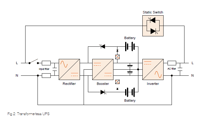
As Fig.2 shows, transformerless UPS systems lack output transformers, so the DC component issue must be handled differently. Software, as well as hardware regulation and control, are used to block any DC component at the output of the UPS power supply so that it cannot be fed to the load. Provision must be made for both inverter and static bypass faults.
If an inverter fault such as an IGBT failing to conduct develops, a DC component will be generated. Transformerless UPS systems will include fully redundant EDCP (electronic dc protection) circuits to ensure that the probability of this component reaching the inverter output is practically zero.
Inverter EDCP circuits in recent UPS designs comprise three parts:
Firstly, redundant DC-component regulation continuously detects and regulates the DC component within a tolerance of ±10mV. A normal mains supply to which all non-protected equipment is exposed has a DC-component tolerance of ±300mV.
Secondly, if the DC component exceeds 4V, the EDCP circuit automatically and instantly transfers the load to bypass. The inverter, rectifier and booster are switched off, the battery is disconnected, and alarms are signaled. To ensure the DC component does not appear on the load side, the power protection system operates at all times, even if the uninterruptible power supply is on but switched to bypass. The DC-component detection, regulation and control circuits in modern transformerless UPS systems are redundant, making the UPS power supplies extremely safe and secure.
Thirdly, a DC component may appear on the output if one IGBT fuse blows and the other IGBT continues to conduct. Modern inverter bridges are designed so that if one of their two fuses blows the other fuse will also automatically blow, preventing the DC component flowing to the load. The probability of a DC component passing through a modern transformerless UPS system is no higher than the probability of a transformer going short circuit and allowing the DC component to pass.
Similar protection is built into the bypass switch. If one of the static bypass SCRs ceases to conduct, the load will be automatically transferred to the inverter within 2 to 5ms in order to avoid a DC component on the load side.
This article was written by KUP, the leading suppliers of uninterruptible power supplies systems. To find out more about our expert UPS maintenance service in Singapore contact us on +65 6302 0702 or email [email protected].