For organisations depending on high volume online transactions, the highest possible data processing availability becomes the dominating requirement. Such organisations typically aspire to an availability of 99.999%, often referred to as ‘five-nines’. Other applications, with less critical loads, trade off between availability, capital costs and operating costs to best match their business priorities. With that in mind, Kenny Green, technical services manager for KOHLER Uninterruptible Power, a KOHLER company, looks at the four classification tiers for data centres and explains the impact they have on UPS power.
TUI tier classification system
Developed by The Uptime Institute (TUI), the Tier Classification and Performance Standard defines four levels of availability for a complete site, ranging from the basic Tier l to the highest-availability Tier lV. The true significance of a data centre’s TUI tier rating arises because it depends on all aspects of the site’s infrastructure that impact operation, including both subsystems installed and operational sustainability. This in turn involves many factors, including topology decisions, about robustness and operability, construction implementation, site management and staffing. The rating is also constrained by the infrastructure’s lowest-rated aspect. For example, a site with a robust Tier lV UPS installation and a Tier ll chilled water system will be limited to a Tier ll site rating.
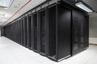
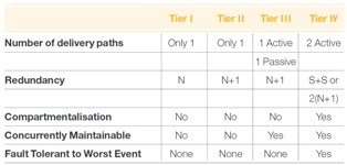
Table 1 shows the key parameters for the standard’s four tiers. The system is based on two variants of two design techniques – dual cording and redundancy.
Dual cording refers to IT equipment that has two independent power inputs, each sufficient to meet its entire power requirement. If any event, anywhere on the data centre site should interrupt one power feed, the other can continue to drive the IT load, without the load suffering power interruption or loss. This is redundancy at the power distribution path level.
Redundancy brings the same type of resilience to failure at a system level, using a technique known as ‘N+1’. In a UPS system, for example, if a configuration with N modules is sufficient to entirely support a critical load, then a configuration containing N+1 modules would continue to support the load without power interruption or loss even if one module fails.
Accordingly, a Tier l basic data centre has non-redundant capacity components and a single, non-redundant power distribution path serving the ICT equipment. Within such a system, conditioned power to the load is lost whenever the UPS has to be shut down for maintenance, or if a fault in the UPS or power line occurs. Tier ll is an improvement on this, as it introduces redundancy in the infrastructure components as indicated by N+1 in Table 1. This gives protection from a single failure and allows a degree of concurrent maintenance.
Tier lll has a dual bus power system connected to critical loads with dual power inputs. It includes Tier ll type redundant capacity component configuration. Typically, only one power bus serves the ICT equipment at any one time. Concurrent maintenance is fully supported. Tier lV, the highest rating, is classified as a fault tolerant site infrastructure. It comprises two physically segregated active power paths, each with an independent Tier ll system. It offers very high availability, concurrent maintenance and near total fault tolerance.
Availability
The ultimate point of achieving a tier classification is the availability that it brings. Availability can be increased either by increasing Mean Time Between Failures (MTBF) or by decreasing Mean Time To Repair (MTTR). It can be calculated using the equation.
Availability = MTBF x 100%
MTBF + MTTR
However, because the data centre’s overall availability is based on that of each of its critical subsystems, each subsystem must achieve a much higher performance, meaning every subsystem has to achieve 99.9994% – the magic Five-Nines – for the data centre to receive the ultimate Tier lV site rating.
The equation shows how MTBF and MTTR can both be varied to produce a target availability. However, in reality, MTTR values must be kept to minimal levels to generate availability levels sufficient for the higher tiers. Additionally, true MTTR calculations must allow for travel time to site and depend on the availability of any required spare parts together with first-time, fast fix capability.
Increased Availability comes at a cost, in terms of both capital and operating expenditure, for Tier classified power systems. Table 2 shows the relative capital costs of different Tiers, using the Tier l figures as a base reference.
Impact of modern UPS technology
Tier lV requirements were recently reduced by TUI from the double-redundant 2(N+1) to 2N, where each system is fully redundant for the other. This raised the UPS module load by several percentage points. Transformerless technology, due to its size and weight saving, has brought much greater efficiency at all loads, designed to achieve over 95%, even at 50% loading. It also allows UPSs to be configured incrementally and right sized to their load. Additionally, many modern systems offer Eco-mode options which enable efficiencies of around 98% even at 10% load. Even users with reservations about subjecting their load entirely to eco-mode may accept using it with one of their two power buses.