In this article, Tan Yu Ming, General Manager at KOHLER Uninterruptible Power, looks at the role of static switches within different UPS architectures, and how they contribute to power availability.
During normal operating conditions, a UPS accepts incoming mains power, conditions it to remove transients, brownouts and any other aberrations, and makes its filtered output available to its critical load. If the mains does fail, the UPS batteries take over the load without interruption until the mains is restored, a backup generator comes online, or the load has had time to shut down gracefully. Alternatively, in a poorly-designed installation, the battery autonomy may simply expire, causing a system crash and all its consequential damage.
A yet further scenario is that the UPS itself fails, or is subjected to an overload condition beyond its capacity. Accordingly, practical UPS installations include a static switch which can select between the UPS inverter output and a raw mains bypass to feed the critical load. In online UPS systems, the switch remains ‘on UPS’ unless a UPS fault develops, in which case it changes over automatically and seamlessly to the raw mains supply. This puts the load at risk from mains-borne power problems, but is preferable to the load losing all power without warning. In any case, the UPS will generate an alarm while on bypass to draw attention to this risk.
In offline UPS systems, however, the static switch feeds the critical load from the raw mains under normal conditions, and only changes to the UPS if the mains fails. Although this allows greater operational efficiency through eliminating losses in the UPS’s rectifier and inverter stages, it means that the critical load is continuously exposed to any incident mains power problems; the UPS provides a battery backup function, but no power protection. For this reason, nearly all data centre operators choose online systems – they regard power protection as essential.
Static switch internal design
The static switch is so-called because it is implemented using semiconductors rather than electromechanical moving parts – and being semiconductor-based, it can provide the fast, break-free transfer essential for effective load protection. The decision to transfer is shared between the static switch’s internal logic and the UPS control system in an installation-specific arrangement; it’s based on continuous monitoring of the inverter and raw mains voltages. Additionally, the control logic typically manages the inverter voltage phase and frequency to facilitate synchronisation between the inverter and mains bypass outputs. This synchronisation is essential to allow bi-directional, break-free transfer between the two power sources.
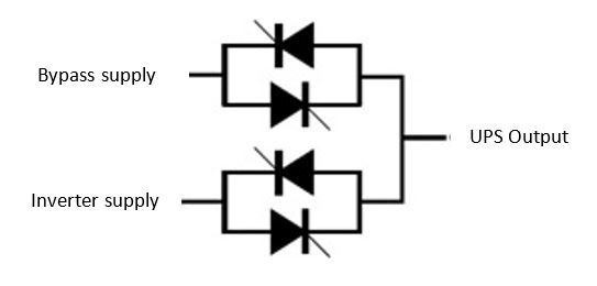
Figure 1 – Simplified static switch design
Figure 1 shows a simplified form of a single-phase static switch’s internal design. It comprises a pair of inverse parallel connected SCRs in series with the bypass and inverter supplies. During normal UPS operation, SCRs 3 and 4 are triggered ON, while SCRs 2 and 3 are triggered OFF; the opposite is true when the switch is selected to Bypass. In a three-phase circuit, the same SCR arrangement is repeated for each of the three-phases.
The triggering is arranged to ensure that bypass and inverter supplies are briefly paralleled; this ensures a break-free transfer, and explains why synchronisation of the supplies is essential. Without this, the load would almost certainly suffer a power disturbance. While the UK’s mains supply frequency is usually very stable, the same may not be true for an onsite standby generator.
The static switch in parallel modular UPS systems
The static switch’s role is a little more complex in multi-module parallel UPS systems, because it depends on whether the UPS has centralised parallel architecture (CPA) or decentralised parallel architecture (DPA).
CPA refers to UPSs that share some common components, including the static switch. The major benefit of CPA is that expensive components such as those used in module control electronics and static switches are shared instead of duplicated, so reducing cost. The downside of this architecture is that the shared components create single points of failure, which adversely affects the UPS’s availability.
By contrast, DPA systems have completely self-contained modules, each with their own control electronics and static switch. This component duplication makes DPA UPS systems costlier, but it also significantly improves their availability by eliminating single points of failure. For most data centre operators, higher availability will always trump cost considerations – within reason.
Figure 2 shows a typical CPA centralised static switch (CSS). The maintenance bypass switch is normally open, and only closed during CSS maintenance. During normal operation, all the UPS modules are synchronised to one another and to the mains supply, and share the load equally. If one UPS module fails, the load is shared equally between the remaining modules. However if they find this load unsustainable, they transfer it to the standby mains via the CSS.
Interlocking circuitry between the CSS and each UPS module prevents the static switch from turning on while the modules are active. This is important because if the static bypass switch and module static switches were simultaneously on, backfeeding of power from the standby mains through the static bypass and into the UPS module output terminals would damage the modules.
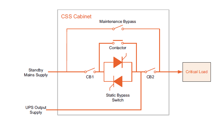
Figure 2 – Typical CSS design
As previously mentioned, DPA systems avoid single points of failure, including central static switches. Instead, all the UPS’s modules are connected in parallel, directly to the load as shown in Figure 3. The total system capacity depends on the individual module ratings and the number of modules used. Each module has its own static bypass switch, which is rated for the full load capacity, including overload. Each module switch supplies the load from either the UPS inverter output or the raw mains supply. The critical load can also be fed from the Maintenance Bypass switch if the UPS must be shut down and taken off line for maintenance or troubleshooting work.
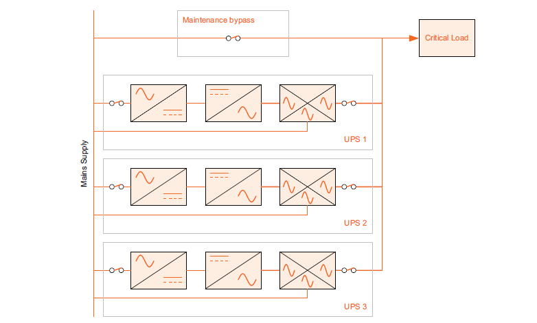
Figure 3 – Three module decentralised UPS system
During normal operation all the UPS modules are on line, with their inverters feeding the load through their internal static switches. All the inverters are synchronised to one another and to the standby mains supply if present, and share the load equally. If a module becomes faulty, it automatically isolates itself from the critical load by inhibiting the inverter side of its static switch. The remaining, healthy modules continue to share the load, provided their combined capacity is sufficient to do so.
If this is not the case, all the modules, including the faulty unit, transfer the critical load to the standby or raw mains via their internal static switches. If the system is synchronised the transfer is break-free and is achieved by enabling the operation of the bypass side, while inhibiting the inverter side of each module’s static switch. However if the system is not synchronised, the UPS modules will not allow any transfer to mains, and instead endeavour to supply the overload for as long as possible before switching off to protect themselves.
Conclusion
Although decentralised control systems once required complex data and signal processing electronics, this is no longer true. Additionally, modern internal static switches offer the same fault clearing capacity as a CSS. Meanwhile, centralised systems typically require a separate CSS cabinet, which adds to their complexity, cost and footprint. When these factors are added to the CSS’s single point of failure risk, it’s easy to see why decentralised parallel systems have become the most popular choice.