Power Usage Effectiveness, or PUE, has become a popular metric for measuring the overall electrical energy efficiency of a data centre. It compares ‘useful’ power used for data processing with total power taken from the grid.
In this article Alan Luscombe, Director at KOHLER Uninterruptible Power, a KOHLER company, looks at the significance of PUE and how modern UPS topology can help to improve it.
What is PUE?
Driven by continuously-growing demand for secure data processing capacity, dedicated data centres have become truly enormous. Colocation provider Switch’s SuperNAP data centre campus in Las Vegas, for example, has a mission-critical power capacity of up to 200MW and can house up to 20,000 cabinets.
As power demand has climbed to these levels, energy efficiency has become a critical issue for both commercial and political reasons. In recognition of this, the Green Grid – an industry group focused on data centre efficiency – created the Power Usage Effectiveness or PUE metric to determine a data centre’s efficiency. PUE is defined as the ratio between the amount of power entering a data centre and the amount usefully consumed by the data-processing load within it. As a data centre’s efficiency improves, its PUE drops; an ‘ideal’, perfectly-efficient data centre would have a PUE of 1.
According to the Uptime Institute’s Data Center Industry Survey 2013, the typical data centre has an average PUE of 1.65, so for every 1.65W taken from the utility, only 1W is used directly for IT activity. The ‘useful’ power is consumed by data processing hardware including servers, storage and telecommunications equipment. The ‘overhead’ is due to chillers and other cooling equipment, switchgear and UPSs. As cooling equipment has become more efficient, attention has turned to UPS systems as they offer the major remaining PUE improvement opportunity.
PUE values can vary continuously over a 24 hour period as data centre loads change, on both the overhead and IT equipment sides. Outside ambient temperature changes can also affect cooling equipment and its contribution to the PUE value. Nevertheless, PUE provides a useful comparative indicator that can reveal improvements and changes within the data centre. One slightly counterintuitive result occurs if a data centre succeeds in bettering its IT hardware’s efficiency – the overall PUE deteriorates. However this effect can be countered, and PUE improved, if UPS energy efficiency is improved. In fact, the benefits are two-fold; in addition to direct energy savings, raised UPS efficiency cuts energy use by reducing cooling requirements. Accordingly, we now look at two ways of improving UPS efficiency.
UPS technology and efficiency
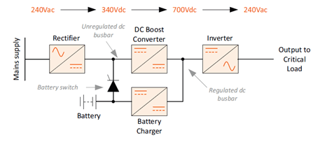
Modern UPS topology has evolved through the availability of improved power semiconductor technology. This has allowed the earlier phase-controlled rectifier design to be replaced by a fixed rectifier and DC boost converter as shown in Fig.1. In this configuration the DC converter’s output voltage remains constant for a fairly wide range of voltages on the unregulated DC busbar, so its output to the regulated busbar is unaffected by AC mains aberrations. It is also permits the UPS inverter to generate an output AC voltage at a level compatible with the incoming utility mains. The battery charger reduces the regulated busbar’s high voltage to a level suitable for battery float charging.
The configuration shown, like its earlier counterpart, is known as a double-conversion online type. During normal operation the rectifier and inverter protect the critical load from mains-borne noise and transient voltage excursions, while providing a well-regulated output voltage. If the mains fails, or exceeds preset voltage limits – typically +10% to -20% – the battery takes over until mains is restored. Transfers between battery and mains are invisible to the load, while regulation and protection also continue without degradation.
Fig. 1: Transformerless UPS block diagram
A UPS (uninterruptible power supply) sits between an alternative source of power – such as a standby diesel generator – and protected loads. Most UPS are designed to power connected loads continuously via their inverter, which also enables conditioning of mains supply voltage and insurance of a break-free supply of electrical energy in the even of a mains failure. In most applications, UPS are considered critical to business continuity without which loads would not be able to operate during a power outage. For this reason, load bank testing is implemented to ensure UPS can meet the requirements of their intended function when most needed.
Load bank testing is a way of validating the correct operational performance and battery autonomy of the UPS system. It tests the UPS and generator under load conditions. It is most often carried out during preventative maintenance. As a UPS battery set is only as strong as its weakest battery cell, load bank testing can also be used to ascertain the condition of UPS batteries and battery sets (or ‘strings’ as they are also known) to indicate if any individual cells are approaching the end of their working life and not holding a charge or about to fail. This enables them to be replaced in advance of critical application.
Load bank testing is offered as a service by suppliers of power protection equipment, such as KOHLER Uninterruptible Power. Some suppliers offer load bank testing as part of the UPS commissioning process but caution must be exercised: ideally it should be carried out at least one week after the UPS has been commissioned to permit the voltage across the battery blocks to equalise and batteries to be fully charged. Load bank testing prior to this will not yield accurate results, or give a true picture of how the system is running, and thus be a waste of time and money.
Suppliers of load bank testing normally carry their own small load banks (typically 100kW or less) and will hire in larger dummy sets to test larger UPS systems as required. These load banks are typically resistive (neither inductive nor capacitive and with no initial switch-on surge. Current rises immediately to a steady state). Load banks are available for either ac or dc systems. An ac load bank is used to test entire UPS systems, whereas a dc load bank will be used to test batteries. Reactive load banks are also available (typically with a lagging power factor 0.8) but they tend to be larger and heavier in design.
What is the point of load bank testing?
The point is to test the power protection system (and component parts) under load conditions but without risking supply to protected loads – just as components in a racing car can be tested in simulators to see if they hold up in race conditions but without risking crashing the actual car itself.
The point about UPS is that operators hope they’re never going to have to use it in earnest – like a fire alarm that sits in silence most of the time until there’s a fire and then blares into action. But what if it didn’t? The same considerations apply with UPS and power protection in general – the time to find out it does not work (or has a fault) is not when mains power fails. Fire alarms need to be tested, as do UPS, periodically, to ensure they will work when required. With a generator, merely starting it up is insufficient. Operators need to know it will actually run, fully loaded. Same as a car – a driver doesn’t just start it up and say “yes, that works”, they actually take it for a drive – and that is what load bank testing does – takes a power protection system for a drive in a controlled environment.
How is it done and what do the results report?
Load banks should be supplied with suitably rated cables, which enable it to be placed no more than 20 metres from the UPS terminals or output power distribution unit (PDU). Load banks comprise heating elements and fans for cooling and allowances should be made for heat dissipation and noise attenuation during the test. Needless to say, it should not be carried out within the vicinity of sensitive alarms, sprinkler systems or close to where people are working.
Measurements are taken during discharge from which it is possible to determine battery and system performance. A load bank test will provide timely identification of problems with the generator and UPS and an indication of remedial actions that should be taken. In the case of a standby generator, a load bank test will indicate the engine’s ability to provide the required power; the alternator’s capability to provide the required voltage stability; stable frequency; efficiency of control systems under varying conditions of load; performance of the whole system; oil and fuel pressure. It will also help remove deposits from pistons, engine castings and exhausts, identify potential weaknesses and record results and any work that needs to be done.
Load bank testing costs include the hire of the equipment (for larger systems) where applicable, engineer time and temporary cable provision and connection. Although maintenance and testing of power protection equipment should be routine and regular, load bank testing itself should be carried out prudently and with caution as it can reduce system resilience, discharge batteries and may, in that case, place connected loads at risk. For these reasons it is normally carried out outside of normal working hours and by experienced professionals.
Load bank testing will ensure that the components within the power protection system will work and perform together as intended when called upon to support a critical load.
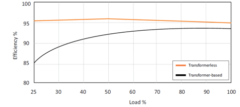
Transformerless technology offers several advantages, of which two are key: Improved efficiency, and significant savings in size and weight. Fig.2 compares transformer-based and transformerless efficiencies against load. Transformerless efficiency is higher across the entire load range, with an overall improvement of around 5%. Cooling costs as well as direct energy losses are substantially reduced.
Fig.2: UPS efficiency curve – transformerless vs. transformer-based solutions
The phase-controlled rectifier within a transformer-based UPS presents a lagging power factor to the mains supply, which moves further from unity as the load reduces. By contrast, the transformerless UPS’s free-running rectifier presents a power factor much closer to unity and far less load-dependent. This reduces the magnitude of the input currents, therefore reducing the size of the power cabling and switchgear. In some instances, electricity running costs are reduced.
As previously mentioned, size and weight are substantially reduced. For example a 120kVA transformer-based UPS would have a 1.32m2 footprint while weighing 1,200Kg. By contrast, a transformerless type occupies 0.64m2 and weighs 310Kg. These reductions in physical dimensions have had an enormous impact on UPS topology, because they have enabled the concept of modular UPS systems. Instead of one large, inflexible unit, a system can comprise a number of rack-mountable modules – each an independent UPS in its own right – paralleled together to provide the overall capacity and redundancy required. Scalability is easy, and if the modules are ‘hot swap’ types, they can be added or removed without having to take the system off line. As modules with capacities from 10KVA are available, UPS capacity can be incrementally and closely matched to the exact load requirement.
This means that transformer-based UPS systems use more energy than their transformerless alternatives for two reasons. Firstly, as Fig. 2 shows, the transformer approach is inherently less efficient. Secondly, as their capacity cannot be incrementally adjusted to their load, transformer types inevitably find themselves operating well below their rated capacity, and as Fig. 2 also shows, this further reduces their efficiency.
As an example, consider a 120KVA load that requires UPS support with N+1 redundancy. The maximum loading per unit of a transformer-based UPS solution would be 50%, if two 120KVA units are used. Efficiency would be 91%. By contrast a transformerless modular UPS solution could achieve N+1 redundancy using four 40KVA modules, with 75% loading and 94.5% efficiency. Based on 9.0p/KWh, the total cost of cooling and energy losses for a year’s operation of the transformer-based UPS would be £13,264; the transformerless figure would be £5,637. Therefore, over five years, £38,135 will be saved by using modular transformerless UPS technology.
Eco-mode operation
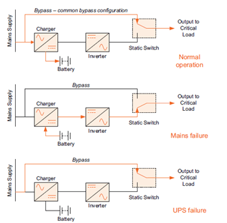
A modern modular UPS system can achieve 96.1% efficiency while operating on-line. For many data centres, this is the default mode. This can be increased to 99% efficiency, or possibly more, by switching to eco-mode. Fig.3 shows the eco-mode principle; in normal operation, the critical load is fed directly from the raw mains. The UPS components and battery back-up only come into use during a mains failure.
The attraction of eco-mode is that bypassing the UPS components during normal operation allows very high efficiencies. The downside is that the critical load is constantly exposed to any noise, spikes or other mains-borne problems. Every data centre manager has to consider the historical power quality of his mains supply and the sensitivity of his on-site equipment, and weigh the exposure risk against the energy-saving benefits of eco-mode.
Fig. 3: UPS system in Eco-mode
Conclusion
In this article we have seen that PUE is a popular metric for data centre power supply efficiency. As data processing equipment efficiency improves, overall PUE can deteriorate. Raising the efficiency of essential support systems such as the UPSs is vital to maintain or improve PUE values. This can be done primarily by using modern UPS hardware based on transformerless technology which offers about a 5% efficiency improvement over traditional transformer-based designs. Efficiency can be taken to 99% or better by operating in eco-mode, however this benefit must be balanced against the risk of exposing the critical load to raw mains during normal operation.